Saturday, March 31, 2012

Turnout - Points, Closure Rails and Frog Rails

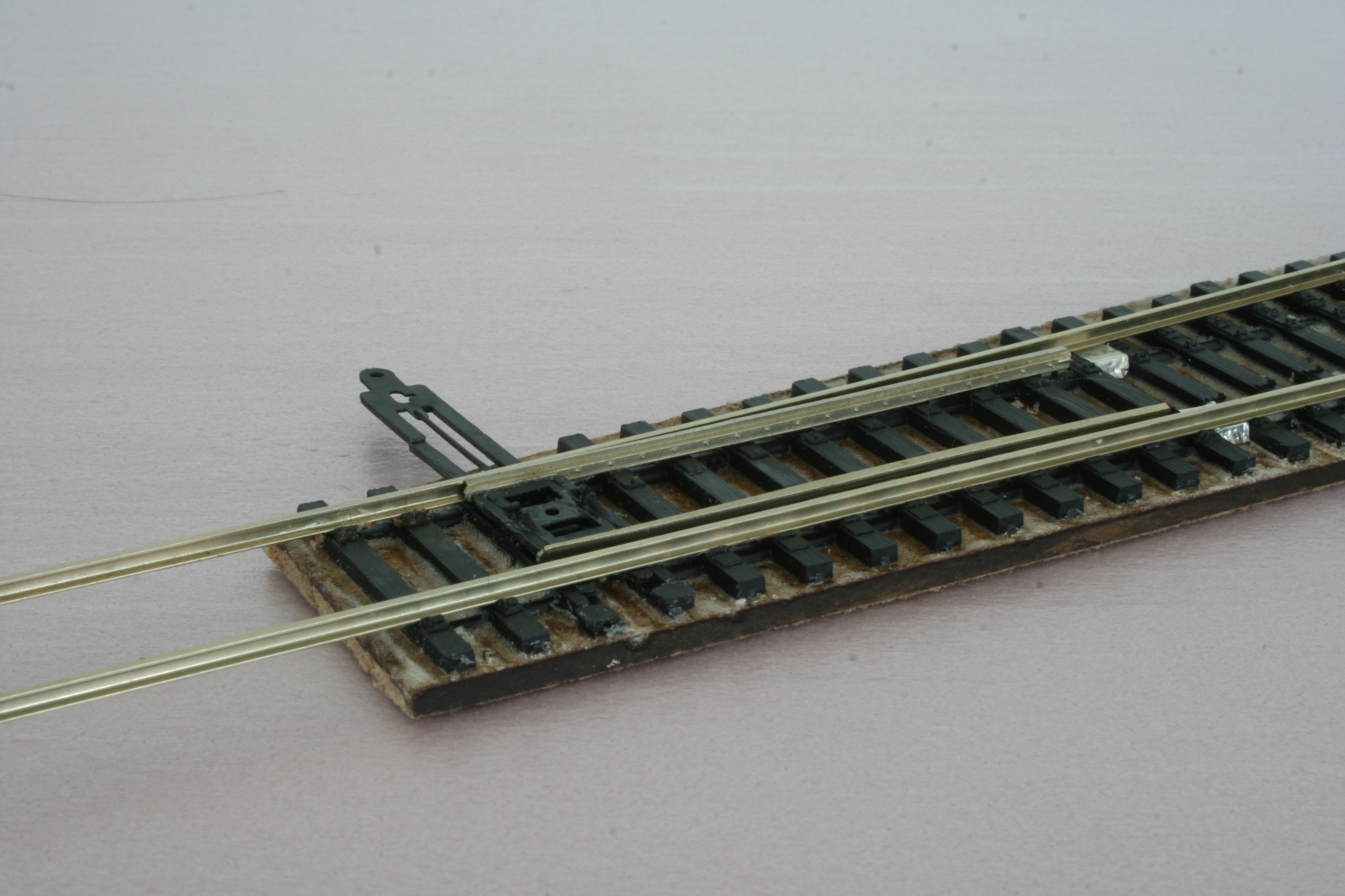
I more or less finished assembly of the #7 turnout today. First the drawbar was slid in place, under the stock rails. Next the points were installed. They hook up to slots in the tie plate. The other end of the points are locked to the drawbar with the help of a retainer plate which is glued to the drawbar.  CVT has made it possible to hook up switch machines and actuating linkage in slightly different ways, but I opted to do it this way since I intend to use my old Tortoise switch machines, mounted straight below the points.


There are small holes in the "hooks" of the points, intended for feeder wires, but of course, I forgot about that although the instructions are clear - solder the wires to the points before installing them. Luckily I managed to solder them in place afterwards, without damaging the ties.


Next came the closure rails. This was straightforward. Pieces of rail are cut to the appropriate length. At the frog end they are partly slid under the earlier installed frog block. At the point end, they simply end where the points begin. The rail for the diverging route had to be slightly bent, but as for the stock rails, the tie plates and the self gauging mechanism makes this a snap. I glued the rails in place with CA.


The frog is formed with two shorter pieces of rails, filed so that they form a sharp point. The CVT instructions explains this fairly well. Once filed and test fitted I glued the rails in place with CA.


Last, I glued styrene bolt bars to the frog block. I also glued rail-braces to the ties along the point area.


The CVT kit also includes parts to make a switchstand. The switch-stand seems quite fragile, so I intend to wait with that until later, when the turnouts are in place on the layout. Painting and weathering will also have to wait.

So for the time being, this turnout has to be considered completed. It looks good so far and was not that difficult to build. Hopefully the next one will be even less difficult and look even better when finished!

Last minute addition: An Ohm-meter showed that the foil strips, supposed to create electrical contact between the stock and closure rails, did not do their job. There simply was no contact. I tried to flood some solder between the foil and the rails, but with limited result. Instead I bent the foil up on top of the rail base, on the outside of each rail. Then it was possible to solder the foil to the rails, making contact. I wonder how this was meant to work reliably in the first place. I have to come up with something better for the future turnouts.

Sunday, March 25, 2012

Turnouts - stock rails and guard rails

Yet another step forward - stock rails and guardrails. I cut lengths of Micro Engineering code 70 nickel silver rail (non-weathered) and bonded them to the tie strips. The tie strips are self-gauging so you more or less need only drop the rails in place. You are however requested to make a small kink in the stock rail for the diverging route, just before the points.

I used Pliobond contact cement, mostly because I had it at hand and have used it before, when laying rail on wood ties. That was in N scale, but I see no reason why a contact cement should not do its job in this application as well.


I also glued the styrene guardrails in place. I used a NMRA track gauge to check the flange ways, and they seemed OK. So far so good.

Here is a closer view.


The shiny spots you can see where the point rails are to begin are pieces of self-adhesive metal foil. They are supposed to electrically connect the stock rails to the points. I hope they will become less visible when everything is in place and has been painted and weathered.

Thursday, March 22, 2012

Turnouts - part 2

The glue I used when binding the tie strips to the hardboard is of the same type as American "Gorilla Glue", and naturally I had forgotten that it expands when it sets. Meaning it oozed up along the sides of the ties. It did not overflow the ties, but I had to do some cutting and peeling with an X-acto knife to remove most of it.

Otherwise construction continued as described in the supplied instructions. The first step was to do some filing and trimming of the points. The points "hook" into the tie plate, and swing around that hook. The points had to be trimmed with a small file to get a proper fit. Also, flash had to be removed from the throw bar and tie block pieces. All of these parts where then laid aside for future use.


Next, the frog block was glued in place. Its proper location given by small tabs on the bottom, fitting into holes in the ties.


Well, that was what I accomplished during this session.

Sunday, March 18, 2012

CVT Turnouts

One of the reasons I wanted to try some H0 modeling was the opportunity to make some detailed turnouts. At least more detailed than standard N scale turnouts (I have done my fair share of N Scale turnout detailing, but with a less good result. You can start reading about that project here. The last post is here).

EDIT September 19, 2022: The above links do no longer work since the blog they are linking to got "lost in translation" some time ago. Sorry about that.
😐

For this H0 project I choose to try the Central Valley Turnout kits. They seem to have a fair amount of detailing and still be easy to build. So some time ago I ordered a #7 kit and a #6 kit, both for code 70 rail. I also ordered a sample pack of "branch line ties" and some Micro Engineering code 70 rail. And a few days ago the parcel arrived. Here are some photos of the content.


Above, to the right of the tie strip, are head block, "drawbar", switch stand, guard rails and so on. The small bag above all that includes the cast points ("white metal") and the plastic frog.


Here is a close up of the "branch line tie strip" (top) and the #6 turnout tie strip (bottom).


Since I have never done any CVT turnouts before I decided to build these two at the workbench, rather that directly on the layout. I cut some hard.board the same shape as the turnout tie strips, and glued down the strips on top. The hard board is exactly the same thickness as the cork subroad I intend to use, so the turnouts should later mate without any problems with the rest of the rail.

Here are the strips on top of the hardboard. The glue is still wet, and whole thing will soon be hidden below some weights (heavy books) while it sets.


Sunday, March 11, 2012

Foam

Today I applied a layer of pink foam on top of the benchwork. I glued it down with ordinary white glue. Not very exciting but a step forward.


Thursday, March 8, 2012

Intermodal Crane

Sometime ago I bought a Walthers Cornerstone Intermodal Crane kit. The crane was quite large, with a width of three tracks or trucks. I decided to make my version less wide, and cut and removed about a third of each girder.

I also substituted the walkways and ladders, with parts from various other manufacturers. This because I found the original parts to be a little on the heavy side. I spray painted the crane parts yellow before assembly. The walkways and ladders were brush painted grey after everything was glued together.

The photos below show how my crane turned out, after painting, decaling and weathering.


Sunday, March 4, 2012

Box Car Detailing

My first H0 freight car investment was three cars from ExactRail - a 60 ft CSX Waffle box car, a CNW covered hopper and a SP Hi-Cube. The two former in the Platinum series and the latter in the Evolution series, meaning it lacked air hoses and cut levers. It also had Kadee #5 couplers, while the other two had #58 couplers. So I sat out to bring the hi-cube up to the same standard as the others.

The couplers was any easy replacement - unscrew the coupler box lid, replace the coupler and screw the lid back.

I fabricated the cut levers from brass rod, which I bent to the correct form using pliers. I mounted the levers on the car using a bracket (a "white metal" casting I bought) and by gluing the end to the underside of the draft box.


I then glued the air hoses to the other side of the draft box, and extended the air piping with a piece of styrene.


Next was painting. The cut levers, brackets and air piping got the same box car red as the car itself, while I painted the air hoses black. Last I gave the nozzle a metal (silver) coating.


And here is the finished car.