I wanted some throw bars or switch stands for my turnouts. The Central Valley Turnout kits I have been using include parts to build a switch stand. A switch stand that is even animated, meaning the target turns as the turnout is thrown! All the same, how nice the CVT stand might be, it is of an older style and I wanted my throw bars to be of a more contemporary design.
 |
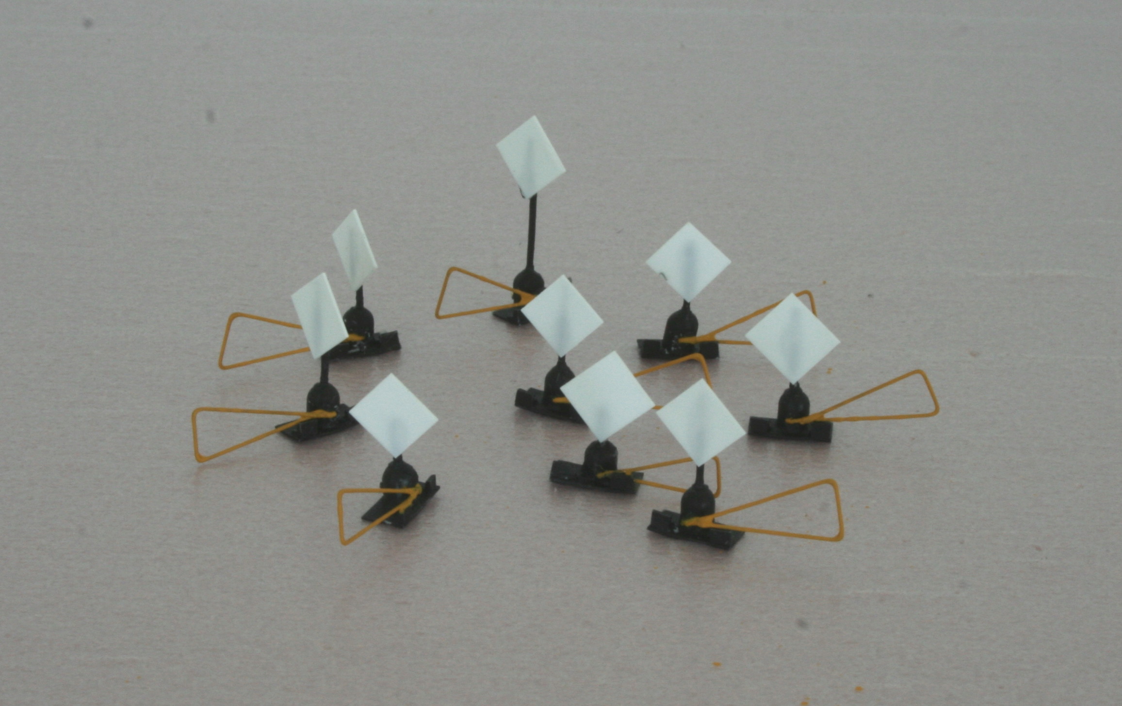
| Sneak preview of one of the switch stands I built. |
So I set out to try to build some throw bars of the so called "back saver" ergonomic kind. A search on the Internet did not result in many pictures of such throw bars but I found two suppliers of prototype throw bars. I used pictures on their web sites as the inspiration for my throw bars. You can see for yourself by following these links:
Unitrac Railroad Materials Inc.
G&B Specialties, Inc.
EDIT September 19, 2022: The above links do no longer take you to any Backsaver throwbars. Times they are a-changin'. Instead; here is a photo I found (Aldon Company Easy Throw switch stand handle):
My intention was not to build exact replicas of any of those throw bars, but something simpler that would still give the correct impression.
I started out by forming a base for the stands from some styrene strip, which I cut to a suitable length, so that each base plate would span the corresponding head ties.
Next I used used parts from an old plastic kit sprue. The cut off pieces would become the gear boxes.
I trimmed the pieces to get a more reasonable gearbox size.
The gearboxes were glued to the base plates. Afterthought: I should have used thicker styrene for the base plates. They have a tendency to warp.
Then I turned my attention to the actual throw levers, which I created from brass wire. I simply bent the wire into the correct shape using tweezers. I did not cut the levers to length at this point. I left a rather long piece for easier handling. I "closed the loop" with a drop of CA.
I wanted some more details than just the base plate and the gearbox, so I cut pieces from styrene L-strip and glued to the base plate of each switch stand. I can't say what prototype feature that represent, but on my models they just add to the "visual complexity" of the equipment.
Using a pine vise I also drilled two holes in each gearbox. One vertical from the top for the target rod, and one horizontal and close to the base for the throw lever. Here is a switch stand with the extra styrene pieces, a rod for the target and a test fitted throw lever. I did not finally attach the throw levers at this point, since I wanted to paint the parts first.
Painting came next. I painted the gear boxes a flat black, and for the levers I used CNW Yellow, which I happened to have at hand.
And once the painted had dried I attached the levers to the gearboxes. Before I thread the "loose" end of each lever through the corresponding hole in the gearbox I made a 90 degree bend on the wire and attached a drop of CA. I also cut the part of the lever wire that protruded on the opposite side of the gearbox.
Using a Northwest Shortline chopper I cut square targets from styrene sheet, and CA:ed to the rods on the stands, after having cut them to length. All of stands are supposed to be "low", except one. The latter will be placed at the mainline turnout.
I then painted the targets red.
And that was it. All that remained was to eventually plant my new throw bars on the layout - I imagined. But when I test fitted one of them on the tightest spot I immediately realized that the targets were to large, as seen in this picture. The turnout it is supposed to operate is to the left.
There was a high risk that the target would be knocked down by passing cars, both due to its width and its height. Even if that would have not been the case, the whole thing did not look very realistic. A real railroad would not have allowed such tight clearances. Well, it might be that they would not put a switch stand in that spot under any circumstances. They might have extended the throw bar so that the switch could be operated from to the right of the right track instead.
I might end up simulating such an setup, or I could place the switch stand to the left of the turnout where it is not that dead tight, but I decided to redo the targets all the same. For better looks.
So I removed the square targets and made new round ones, significantly smaller, instead using a hole puncher.
I cut down the target rods to make the stands as low as possible and glued the new targets in place.
An painted them red.
A test fit in the same tight spot shows that clearances, and looks, have improved.
I will not install the throw bars right now. It will have to wait until the track is painted and ballasted. But it is nice to know that they are there - waiting.
Incidentally, when I had nearly completed my switch stands I happened to stumble upon a video of a guy building back saver switch stands in nearly exactly thefashion as I did. You can check it out here:
Back saver switch stand video