Sunday, December 9, 2012

Bumpers done

The bumping posts are finally painted and weathered. The rust patches are maybe a little to distinct, but otherwise they make do.


Sunday, November 18, 2012

Building bumpers

This weekend I built myself some bumpers, for my yard tracks and spurs. I made a total of five Hayes style bumpers. I began by searching the Internet for some pictures and information on bumpers. On the Western-Cullen-Hayes, Inc. web page I stumbled upon this Bumping Posts Facts and Dimensions brochure. Perfect, with pictures, explanatory text and dimensions. Everything I needed.

I first tried to build a free-standing bumper, with the intention of installing on the track when it was complete. It turned out that was not that easy. For starters, it was difficult to get the correct dimensions. Not only should the bumper if possible have the same dimensions as a real bumping post, as specified in the brochure. It should also fit the model track. These two constraints turned out to not be 100% compatible. It was also hard to get the bumper square and even. Anyway, this was what I ended up with, built from different pieces of styrene.


It looks quite alright, and served part of its purpose; I got the general hang of how to build a bumper. But I decided to switch methods and build the bumpers in place instead.

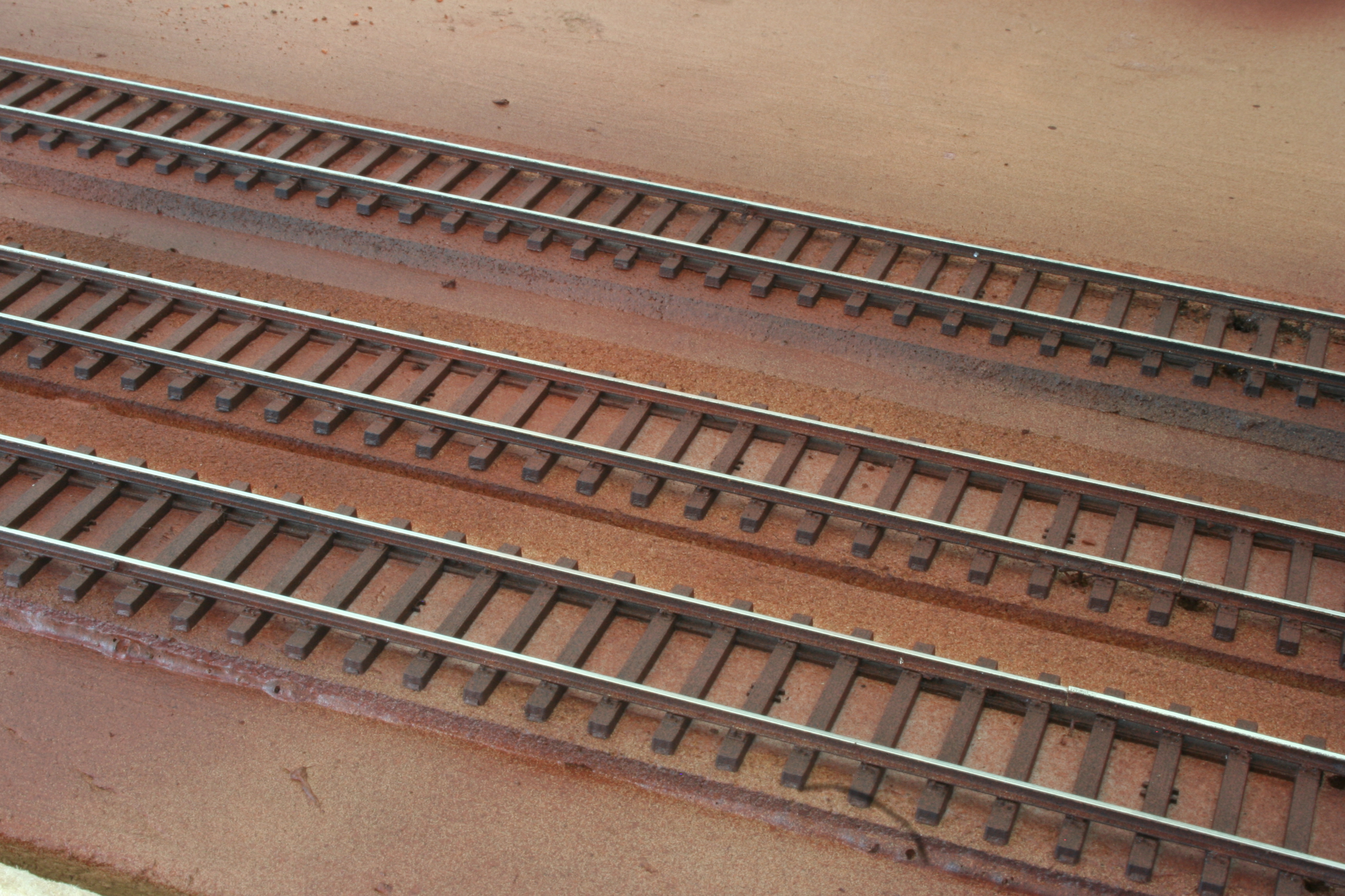
So I started by gluing pieces of styrene angle along two ties on each track. Those are the reinforcement bars extending in under the rails, that help keeping the bumper in place when hit by a car.


Next I cut the so called compression members from .080" (2mm) styrene H-column. I cut them at an angle, beveled the ends and glued them together two and two.


Then I glued the paired compression members to the track, resting on the earlier installed reinforcements bars. I used pieces of MDF board as supports while the glue set.


And this is what it looked like so far, with the temporary supports removed.


Using a car to test fit the height. The head should eventually end up at the same height as the coupler on the car.


Next it was time for the tension members.I fabricated those out of a single piece of .010x.060" (0.25x1.5mm) styrene strip, which I first glued to the top of the compression members and then bent down to the track. To make the strip really bend, instead of breaking, I put on dabs on styrene cement where the bends would go. This softens the styrene and makes it possible to bend.


Last, I made the head from .080" (2mm) square rod and some .01x.125" (0.3x3.2mm) styrene strip. I really needed a rod with a triangular profile, to get the front surface of the head (where the cars hit) vertical. Since I only had square rod at hand, I had to file and shape it to make its profile triangular.

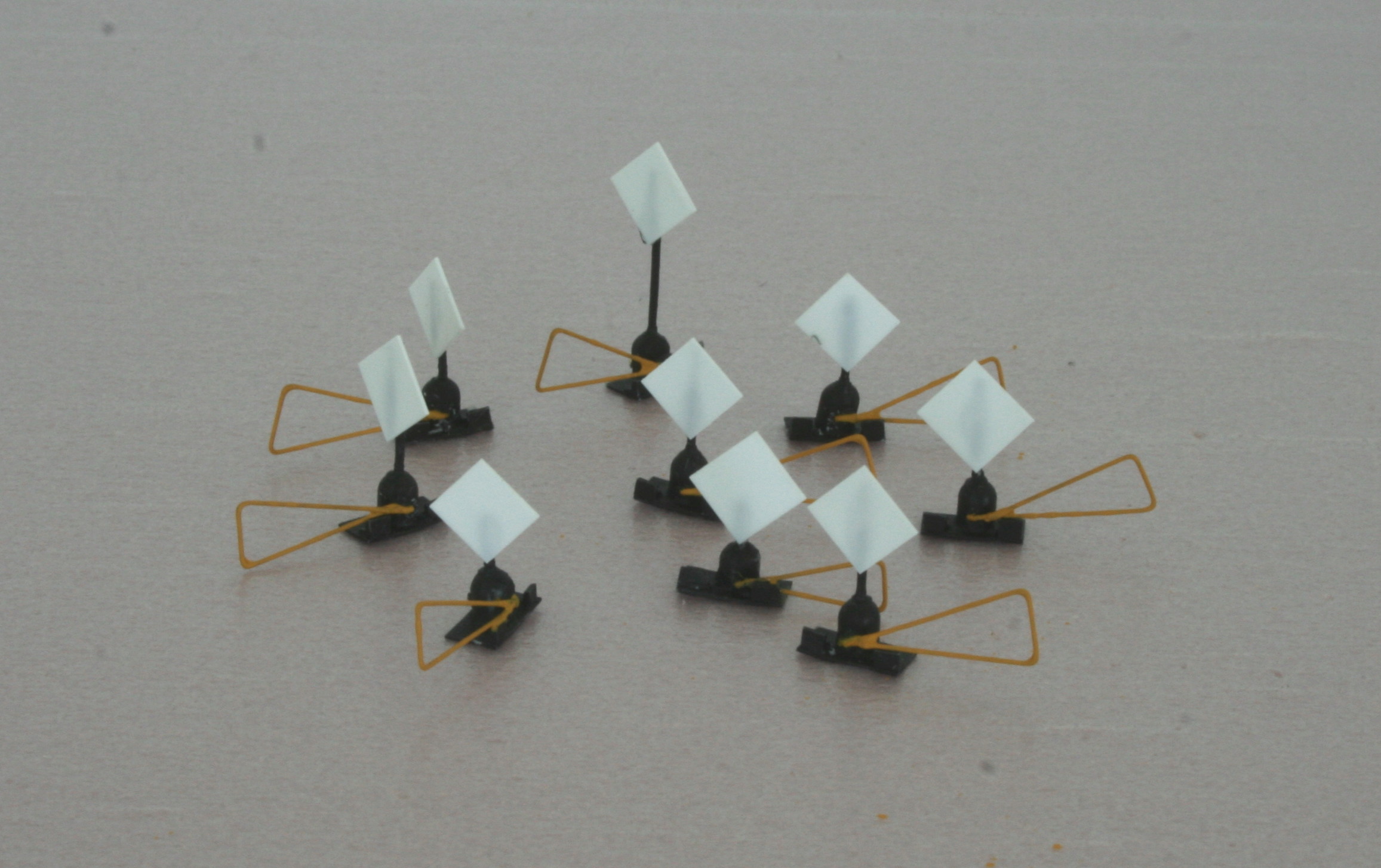
Here the heads are mounted, along with some "bolt bars", to make it believable that the bumper is actually attached to the rails.


Next the bumpers need some paint, and weathering.

Thanks for watching.

Saturday, November 10, 2012

Flat finish

Some flat finish effectively kills the sheen on the retaining wall.


Wednesday, November 7, 2012

Retaining wall

I needed a break from all the tie plate weathering and decided to do the retaining wall between the main line and the yard. I had already obtained two Chooch H0 Medium Cut flexible stone walls for that purpose, and was eager to try them out.

The walls are made of some rubber like material and are already painted and weathered. And they are self adhesive. They are easily cut with scissors or a hobby knife. I used both types of tools to cut them to height and stick them to the foam.


I cut three lower walls from each Chooch wall section, for a total of six lengths.

I used 1/8" styrene channel to simulate concrete slabs lying in a row on the top of the walls. I scribed the styrene at 1 centimeter (about 1/3") intervals to simulate the individual slabs.


Then I cemented the channels on top of the wall sections.


Last I brush-painted the styrene with a mixture of light gray and tan colors. Once the paint was dry I followed up with some black weathering powder.


I think the slabs blend nicely with the stones in the wall. Looking closely at the photos I realize the walls would benefit from an over-spray of a flat varnish or similar, to kill the sheen.

An easy and rewarding project. Thanks for looking.

Monday, October 29, 2012

Another go at the hardware

I made another go at applying rust to the tie plates. This time with oil paints. A mix of umber and ochre.


This time the rust stayed on the tie plates and did not spread all over the place. But still a little to distinct perhaps. Needs to be toned down a bit, maybe with some powder. But that has to wait until the paint has dried. Or just a darker rust color?

Sunday, October 28, 2012

Weathering track

I have continued the track weathering task. This weekend I tried to age the ties by giving them a gray, and hopefully sun-bleached look. For this purpose I used titanium white and ultramarine blue oil paints. I mixed a larger blob of white with a smaller blob of blue, resulting in a pale blue mix.


I then sort of dry-brushed that mixture on to the ties, which gave them a light gray tone. I tried to not give all the ties the same amount of paint, but strived for some variety. I'm not sure if that was a successful attempt or not.


When I finally had painted all the track, I could not resist a quick test with my new weathering powders. I applied some rust on some of the tie plates, but think I perhaps was a little to generous with the powder. I need to apply the rust more sparingly.


Thanks for looking.


Wednesday, October 24, 2012

Painted points

When spray painting the track, as I showed in the previous post, I had covered the point areas with masking tape, since I did not want any paint to cause the moving points to stuck. So the next obvious step was to brush paint those areas.

I used the same approach as when spray painting - first some reddish/brownish paint, and then a thin layer of black. I used box car red followed by grimy black.

But before painting I replaced the CVT tie blocks with some I did from leftover CVT ties. The original CVT blocks where simply too long to fit between parallel tracks.

Here is a shot of the result.


Next I will use oil paints to add some individuality, and "old age gray", to the ties. And some rust on the spikes and tie plates. More on that in a future post.

Sunday, October 14, 2012

Painting track

For no apparent reason nothing has been accomplished on the layout lately. But yesterday I all of a sudden found myself standing in front of it, with spray cans in hand. Time to paint the track.

Since I was satisfied with track weathering tests I did earlier I proceeded along the same lines. This meant I started by spray painting everything a brownish red color (after having covered the switch point and throwbar areas with masking tape). Like this.


In the picture above I have not only painted the track, I have also cleaned the rail tops. I did that although I was not yet done with the spraying, but I though it wiser to clean one layer of paint at the time, rather than two layers later.

Today I sprayed the track with a black paint, followed by a flat varnish. here is the result, after I removed the switch point masking tape.


Then it was time to clean the rail tops again. I had earlier, by pure chance, that small pieces of MDF board could be used for this purpose. With the advantage that when eventually too dirty, you can simply clean with a few strokes of an ordinary rasp or file.


And here it is all done, more or less.


The next step will be to brush paint the switch point areas.

Sunday, September 9, 2012

Photo container

Inspired by Lance Mindheim, I sat to build some containers from styrene and photos of actual containers. The first thing to do was of course to get some photos, and this time I did not have to look far since a couple of days ago a pair of 20 ft containers were put down at a construction site near my home. Today I went there to take some photos. Here is one of them.


Once back home I fired up an image processing program on my computer (GIMP 2, a freeware program). Using its "perspective" tool I made the container images square. I then, after some struggling with the software, managed to print them in the correct H0 size.

I then built a container sized box from 1mm sheet styrene. Here is the box, and some of the printed and photos, cut to size.


Then all that was left was to glue the photos to the box, like this.


I could do some adjustments at the corners, where the photos partly overlap, but apart from that I think it came out nicely.

Edit: I could also have used better paper and printed at a higher resolution. Now I used ordinary letter paper and standard "everyday" printing settings.


Sunday, September 2, 2012

Track Weathering, part 2

Today I tried to fade the red and yellow tones on the ties. I used a mix of  white and ultra-marine, which I dry brushed on the ties. Looks better I think. A more aged look.


So now I can proceed and spray and weather the rest of the track - about 99% more than this little test stretch.

Saturday, September 1, 2012

Track Weathering

I have done some experimenting with track weathering. I started by spray painting the track a brown color, using a spray can. It was not a carefully selected color. Just a can I happened to find in a nearby store. It was a rather light reddish brown, so I also toned everything down with a light spray of flat black. This is what the track looked like after that treatment.


I then tried different ways, and different kind of colors, to get a more aged and rusty look. I think my best attempt so far was with some oil paints, ochre and burnt sienna. Using a flat and thin brush I applied ochre to the tie plates, and dry brushed ochre and burnt sienna to the ties. I then smeared everything with my finger. The rail sides also got some more color.


Perhaps still a little to much on the red and yellow side. At the next attempt I will maybe try to add some white and ultra-marine. At this time I decided to press on and to see what it would like with ballast in place. So I added some (N scale) ballast, but did not secure it.


It seems I have a fibre or something on my camera lens. Need to get rid of that!

EDIT September 19, 2022: I did finally get rid of the "thing" in the camera sometime during spring of 2022. 😀

Sunday, August 26, 2012

Throw Bars - Backsaver Style

I wanted some throw bars or switch stands for my turnouts. The Central Valley Turnout kits I have been using include parts to build a switch stand. A switch stand that is even animated, meaning the target turns as the turnout is thrown! All the same, how nice the CVT stand might be, it is of an older style and I wanted my throw bars to be of a more contemporary design.

Sneak preview of one of the switch stands I built.


So I set out to try to build some throw bars of the so called "back saver" ergonomic kind. A search on the Internet did not result in many pictures of such throw bars but I found two suppliers of prototype throw bars. I used pictures on their web sites as the inspiration for my throw bars. You can see for yourself by following these links:

Unitrac Railroad Materials Inc.
G&B Specialties, Inc.

EDIT September 19, 2022: The above links do no longer take you to any Backsaver throwbars. Times they are a-changin'. Instead; here is a photo I found (Aldon Company Easy Throw switch stand handle):


My intention was not to build exact replicas of any of those throw bars, but something simpler that would still give the correct impression.

I started out by forming a base for the stands from some styrene strip, which I cut to a suitable length, so that each base plate would span the corresponding head ties.


Next I used used parts from an old plastic kit sprue. The cut off pieces would become the gear boxes.


I trimmed the pieces to get a more reasonable gearbox size.


The gearboxes were glued to the base plates. Afterthought: I should have used thicker styrene for the base plates. They have a tendency to warp.


Then I turned my attention to the actual throw levers, which I created from brass wire. I simply bent the wire into the correct shape using tweezers. I did not cut the levers to length at this point. I left a rather long piece for easier handling. I "closed the loop" with a drop of CA.


I wanted some more details than just the base plate and the gearbox, so I cut pieces from styrene L-strip and glued to the base plate of each switch stand. I can't say what prototype feature that represent, but on my models they just add to the "visual complexity" of the equipment.


Using a pine vise I also drilled two holes in each gearbox. One vertical from the top for the target rod, and one horizontal and close to the base for the throw lever. Here is a switch stand with the extra styrene pieces, a rod for the target and a test fitted throw lever. I did not finally attach the throw levers at this point, since I wanted to paint the parts first.


Painting came next. I painted the gear boxes a flat black, and for the levers I used CNW Yellow, which I happened to have at hand.


And once the painted had dried I attached the levers to the gearboxes. Before I thread the "loose" end of each lever through the corresponding hole in the gearbox I made a 90 degree bend on the wire and attached a drop of CA. I also cut the part of the lever wire that protruded on the opposite side of the gearbox.


Using a Northwest Shortline chopper I cut square targets from styrene sheet, and CA:ed to the rods on the stands, after having cut them to length. All of stands are supposed to be "low", except one. The latter will be placed at the mainline turnout.


I then painted the targets red.


And that was it. All that remained was to eventually plant my new throw bars on the layout - I imagined. But when I test fitted one of them on the tightest spot I immediately realized that the targets were to large, as seen in this picture. The turnout it is supposed to operate is to the left.


There was a high risk that the target would be knocked down by passing cars, both due to its width and its height. Even if that would have not been the case, the whole thing did not look very realistic. A real railroad would not have allowed such tight clearances. Well, it might be that they would not put a switch stand in that spot under any circumstances. They might have extended the throw bar so that the switch could be operated from to the right of the right track instead.

I might end up simulating such an setup, or I could place the switch stand to the left of the turnout where it is not that dead tight, but I decided to redo the targets all the same. For better looks.

So I removed the square targets and made new round ones, significantly smaller, instead using a hole puncher.


I cut down the target rods to make the stands as low as possible and glued the new targets in place.


An painted them red.


A test fit in the same tight spot shows that clearances, and looks, have improved.


I will not install the throw bars right now. It will have to wait until the track is painted and ballasted. But it is nice to know that they are there - waiting.

Incidentally, when I had nearly completed my switch stands I happened to stumble upon a video of a guy building back saver switch stands in nearly exactly thefashion as I did. You can check it out here: Back saver switch stand video