Saturday, June 16, 2012

Preparing fascia for toggle switches

Before I could wire the switch machines I needed somewhere to put he toggle switches. In turn meaning I needed a fascia.

I used hardboard for the fascia. Fortunately I had a few strips left over from when I did the fascia for the previous layout. I started by clamping the hardboard to the bench work. With a pencil I then traced the terrain contour on the back of the hardboard. I removed the hardboard strips and cut them along the pencil trace, and clamped them back again. This is a picture of the progress at that point.


To make things more convenient while I worked along I flipped the whole layout over, letting it rest on its back. I marked the locations of the toggle switches, and then drilled pilot wholes right through both the fascia  hardboard and the bench work.


With the fascia once again removed I then drilled larger holes in the bench work, using the pilot holes to find the proper location for each hole. The holes are large enough to contain the toggle switches.


To avoid damaging the switch machines and wiring when the drill bit eventually came through, I clamped an extra piece of wood "below", as can be seen above. I could then stop drilling when I reached into that piece and avoid to falling through with a bang.

Making these large holes turned out to me a rather messy affair.


But when all the sahavings had been cleaned away it all looked rather neat.


Then it was time to put the fascia back for good, after I had enlarged the pilot holes so that the toggle switches would fit. Here CNW 1316 is posing above a newly test installed toggle switch.


While I was doing the fascia I took the opportunity to expand the layout at one end. The bench work for this layout has been taken from my previous layout, after having been cut down to make it less deep. But the backdrop at one end is still sized after the old layout depth. So now I made a small extension. Like this.


And then letting the fascia curve out like this.


I want the main line, that runs along the edge of the layout, to not just come to a dead end at the backdrop. The extension will help me build some kind of structure or building that the tracks can disappear under. Or something else like that... Anyway, I think the extension, small as it is, will come in handy.

Sunday, June 10, 2012

All switch machines in place

Today I got all the switch machines in place, although not yet electrically wired. Here is a photo of seven of them. There are two more of them further to the left.


Thursday, June 7, 2012

Switch Machines

I have begun to fit the Tortoise switch machines. Since I have no plywood or board of any kind beneath the pink foam I needed to add some before I could proceed. I cut pieces of Medium Density Fiberboard (MDF), two for each machine. One piece for the actual Tortoise and one for the terminal strip I already had connected to each machine. I did that for a previous layout and the strips come in handy when the machines are moved to a new layout. Makes the electrical connection much easier. The reason I used MDF was just because I happened to have a piece lying around.

Here is a picture of the two pieces of MDF for one machine, glued to the foam with "No Nails". The hole for the actuating wire was made from above, at an earlier time when I built the turnout (in place).


And here a switch machine in place. Tested and working on the first try, but not yet permanently connected electrically. 


The second machine was not that easy. The actuating wire needed some tweaking before the turnout worked as it should.

Sunday, June 3, 2012

Wiring

With all the frog rails done, for all of the turnouts, its was time to turn to wiring. The layout is not attached to the shelves which it sits on, it just, that's right, sits on the shelves. This makes it possible to turn it over, letting it rest on the backdrop, so that the underside can be reached. But for this to be possible I needed to get all of the tools and loose stuff out of the way. I took the opportunity to take a photo when everything look tidy for once in a while.


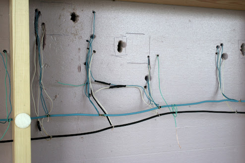
Then I turned the layout over to reveal all the loose wires. There is one wire for every single piece of track. Here are some of them.


After soldering them to the bus wires it looked better. Not "nuclear plant standard" but good enough for a model railroad. At least for mine. The loose green wires are coming from the frogs. Each such wire will be attached to the corresponding switch machine, providing electricity that changes polarity when the switch is thrown.


The larger holes is were the actuator rods from the switch machines will be. To install the switch machines will be the next task. I think I have seven Tortoise machines, meaning I need to get two more. I'd better go and count them.