EDIT September 19, 2022: I did finally get rid of the "thing" in the camera sometime during spring of 2022. 😀
Saturday, September 1, 2012
Track Weathering
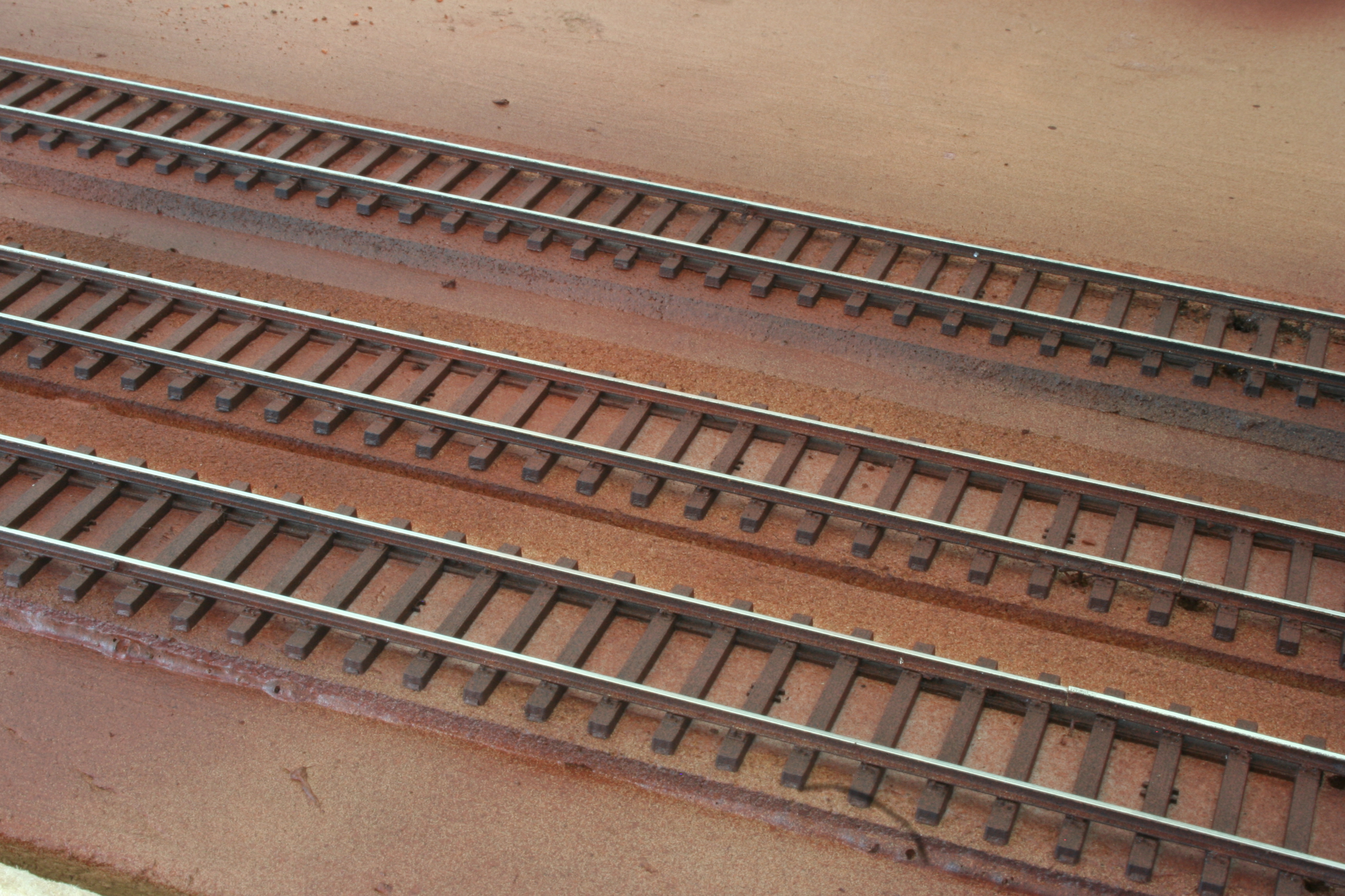
I have done some experimenting with track weathering. I started by spray painting the track a brown color, using a spray can. It was not a carefully selected color. Just a can I happened to find in a nearby store. It was a rather light reddish brown, so I also toned everything down with a light spray of flat black. This is what the track looked like after that treatment.
I then tried different ways, and different kind of colors, to get a more aged and rusty look. I think my best attempt so far was with some oil paints, ochre and burnt sienna. Using a flat and thin brush I applied ochre to the tie plates, and dry brushed ochre and burnt sienna to the ties. I then smeared everything with my finger. The rail sides also got some more color.
Perhaps still a little to much on the red and yellow side. At the next attempt I will maybe try to add some white and ultra-marine. At this time I decided to press on and to see what it would like with ballast in place. So I added some (N scale) ballast, but did not secure it.
It seems I have a fibre or something on my camera lens. Need to get rid of that!
Sunday, August 26, 2012
Throw Bars - Backsaver Style
I wanted some throw bars or switch stands for my turnouts. The Central Valley Turnout kits I have been using include parts to build a switch stand. A switch stand that is even animated, meaning the target turns as the turnout is thrown! All the same, how nice the CVT stand might be, it is of an older style and I wanted my throw bars to be of a more contemporary design.
So I set out to try to build some throw bars of the so called "back saver" ergonomic kind. A search on the Internet did not result in many pictures of such throw bars but I found two suppliers of prototype throw bars. I used pictures on their web sites as the inspiration for my throw bars. You can see for yourself by following these links:
Unitrac Railroad Materials Inc.
G&B Specialties, Inc.
My intention was not to build exact replicas of any of those throw bars, but something simpler that would still give the correct impression.
I started out by forming a base for the stands from some styrene strip, which I cut to a suitable length, so that each base plate would span the corresponding head ties.
Next I used used parts from an old plastic kit sprue. The cut off pieces would become the gear boxes.
I trimmed the pieces to get a more reasonable gearbox size.
The gearboxes were glued to the base plates. Afterthought: I should have used thicker styrene for the base plates. They have a tendency to warp.
Then I turned my attention to the actual throw levers, which I created from brass wire. I simply bent the wire into the correct shape using tweezers. I did not cut the levers to length at this point. I left a rather long piece for easier handling. I "closed the loop" with a drop of CA.
I wanted some more details than just the base plate and the gearbox, so I cut pieces from styrene L-strip and glued to the base plate of each switch stand. I can't say what prototype feature that represent, but on my models they just add to the "visual complexity" of the equipment.
Using a pine vise I also drilled two holes in each gearbox. One vertical from the top for the target rod, and one horizontal and close to the base for the throw lever. Here is a switch stand with the extra styrene pieces, a rod for the target and a test fitted throw lever. I did not finally attach the throw levers at this point, since I wanted to paint the parts first.
Painting came next. I painted the gear boxes a flat black, and for the levers I used CNW Yellow, which I happened to have at hand.
And once the painted had dried I attached the levers to the gearboxes. Before I thread the "loose" end of each lever through the corresponding hole in the gearbox I made a 90 degree bend on the wire and attached a drop of CA. I also cut the part of the lever wire that protruded on the opposite side of the gearbox.
Using a Northwest Shortline chopper I cut square targets from styrene sheet, and CA:ed to the rods on the stands, after having cut them to length. All of stands are supposed to be "low", except one. The latter will be placed at the mainline turnout.
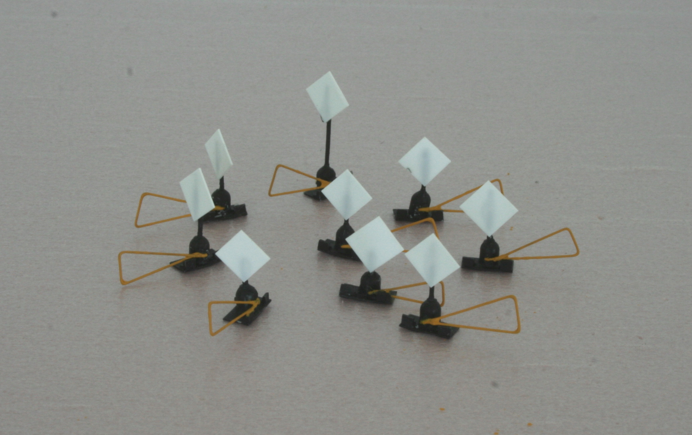
I then painted the targets red.
And that was it. All that remained was to eventually plant my new throw bars on the layout - I imagined. But when I test fitted one of them on the tightest spot I immediately realized that the targets were to large, as seen in this picture. The turnout it is supposed to operate is to the left.
There was a high risk that the target would be knocked down by passing cars, both due to its width and its height. Even if that would have not been the case, the whole thing did not look very realistic. A real railroad would not have allowed such tight clearances. Well, it might be that they would not put a switch stand in that spot under any circumstances. They might have extended the throw bar so that the switch could be operated from to the right of the right track instead.
I might end up simulating such an setup, or I could place the switch stand to the left of the turnout where it is not that dead tight, but I decided to redo the targets all the same. For better looks.
So I removed the square targets and made new round ones, significantly smaller, instead using a hole puncher.
I cut down the target rods to make the stands as low as possible and glued the new targets in place.
An painted them red.
A test fit in the same tight spot shows that clearances, and looks, have improved.
I will not install the throw bars right now. It will have to wait until the track is painted and ballasted. But it is nice to know that they are there - waiting.
Incidentally, when I had nearly completed my switch stands I happened to stumble upon a video of a guy building back saver switch stands in nearly exactly thefashion as I did. You can check it out here: Back saver switch stand video
| Sneak preview of one of the switch stands I built. |
Unitrac Railroad Materials Inc.
G&B Specialties, Inc.
EDIT September 19, 2022: The above links do no longer take you to any Backsaver throwbars. Times they are a-changin'. Instead; here is a photo I found (Aldon Company Easy Throw switch stand handle):
My intention was not to build exact replicas of any of those throw bars, but something simpler that would still give the correct impression.
I started out by forming a base for the stands from some styrene strip, which I cut to a suitable length, so that each base plate would span the corresponding head ties.
Painting came next. I painted the gear boxes a flat black, and for the levers I used CNW Yellow, which I happened to have at hand.
And that was it. All that remained was to eventually plant my new throw bars on the layout - I imagined. But when I test fitted one of them on the tightest spot I immediately realized that the targets were to large, as seen in this picture. The turnout it is supposed to operate is to the left.
I might end up simulating such an setup, or I could place the switch stand to the left of the turnout where it is not that dead tight, but I decided to redo the targets all the same. For better looks.
So I removed the square targets and made new round ones, significantly smaller, instead using a hole puncher.
A test fit in the same tight spot shows that clearances, and looks, have improved.
Incidentally, when I had nearly completed my switch stands I happened to stumble upon a video of a guy building back saver switch stands in nearly exactly thefashion as I did. You can check it out here: Back saver switch stand video
Labels:
backsaver,
ergonomic,
switch stand,
switchstand,
throw bar,
throw lever
Thursday, August 2, 2012
Diamond, part 3
Continued on the crossing. First I did the guard rails for the approach tracks.As you can see in the picture below I glued them to the ties and soldered them to the crossing tracks.
Next up was the U-shaped rails forming the guard rails, and actual rails in the middle of the crossing, for the other set of approach tracks. For those I took the easy route and bent the complete structure from a single piece of rail, as shown in the next picture. In that picture you can also see how I did the guard rails in the middle of the diamond.
I decided to use a piece of styrene sheet as a supporting base for the rails forming the actual diamond. This due to the (very) limited number of ties supporting each individual piece of this structure. Remember, the diamond shaped piece needs to be cut into four individual pieces in order to avoid shorts across the diamond when a loco is passing. I found out that if I used 0.3 mm styrene and code 40 rail I would obtain the same height as for code 55 rail (which is the rail height used for the rest of the crossing.
I cut and bent four L-shaped pieces of rail to form the diamond, with styrene sheet between them to form electrical gaps. This picture shows the progress when three of the four pieces are in place.
And here is a picture of the central piece, with all rail in place and the gap insulators cut back.
Before permanently installing this part in the middle of the crossing I removed the styrene in the middle and painted the outer edges black.
And here is the completed crossing, with all the required electrical gaps done with a Dremel tool. Not the most perfect crossing (I am far to impatient to ever construct the "perfect" piece of track work), but it certainly looks good enough in real life. The camera is unforgiving as usual.
Next I hooked up the electrical feeders, except for the ones to the Auto Reverser. I intended to test the crossing without the reverser first, to make sure there were no basic problems like shorts. So once the wires were in place I run my MP15 towards the crossing, expecting it to stop somewhere in the middle of the crossing (where there was no power). But to my surprise it just moved right through, without the slightest sign of hesitation. And the same thing for the other, crossing, track.
It turned out the distance between the first and last wheels is greater than the length of the unpowered part of the crossing, and the crossing does not need to be powered!
So all my worries, and the investment in a an Auto Reverser, were unnecessary. I'll save the reverser for some other project.
To summarize - a happy ending on a fun project. Below a picture of some test switching across the diamond.
Next up was the U-shaped rails forming the guard rails, and actual rails in the middle of the crossing, for the other set of approach tracks. For those I took the easy route and bent the complete structure from a single piece of rail, as shown in the next picture. In that picture you can also see how I did the guard rails in the middle of the diamond.
I decided to use a piece of styrene sheet as a supporting base for the rails forming the actual diamond. This due to the (very) limited number of ties supporting each individual piece of this structure. Remember, the diamond shaped piece needs to be cut into four individual pieces in order to avoid shorts across the diamond when a loco is passing. I found out that if I used 0.3 mm styrene and code 40 rail I would obtain the same height as for code 55 rail (which is the rail height used for the rest of the crossing.
I cut and bent four L-shaped pieces of rail to form the diamond, with styrene sheet between them to form electrical gaps. This picture shows the progress when three of the four pieces are in place.
And here is a picture of the central piece, with all rail in place and the gap insulators cut back.
And here is the completed crossing, with all the required electrical gaps done with a Dremel tool. Not the most perfect crossing (I am far to impatient to ever construct the "perfect" piece of track work), but it certainly looks good enough in real life. The camera is unforgiving as usual.
Next I hooked up the electrical feeders, except for the ones to the Auto Reverser. I intended to test the crossing without the reverser first, to make sure there were no basic problems like shorts. So once the wires were in place I run my MP15 towards the crossing, expecting it to stop somewhere in the middle of the crossing (where there was no power). But to my surprise it just moved right through, without the slightest sign of hesitation. And the same thing for the other, crossing, track.
It turned out the distance between the first and last wheels is greater than the length of the unpowered part of the crossing, and the crossing does not need to be powered!
So all my worries, and the investment in a an Auto Reverser, were unnecessary. I'll save the reverser for some other project.
To summarize - a happy ending on a fun project. Below a picture of some test switching across the diamond.
Wednesday, August 1, 2012
Diamond, part 2
I have been working some on my diamond crossing. But before I dived in I drew a diagram of the rails, how they relate electrically and where I need to cut gaps in order to avoid shorts.
As can be seen in the picture the upper two rails have the same polarity (A), and they need not to be cut. The same goes for the lower rails, both having polarity B. The "middle" rails however, both to the left and to the right in the picture, have opposite polarities. So they cannot be connected together. An electrically separate section is required in both locations, and those sections (R1 and R2 in the picture) need to change polarity depending on whether an engine approaches on the upper track or on the lower track. Here is where my newly acquired Auto Reverser comes in.
In addition, the guard rails need to be cut to avoid possible shorts created by a passing engine.
The photo below shows the first pair of rails glued in place, going straight through the crossing. I decided to do it like that, and cut the rails later, in order to get a smooth curve through the diamond (yes, the entire diamond is curved in both directions).
Next, I installed the rails for the other track.
The crossing track rails run right up to the first pair of rails, and are soldered to those tracks. I had to do some intricate filing of the rails to get them to fit together, for the solder to be able to make a solid joint.
Coming next - guard rails (and more).
Thanks for watching.
In addition, the guard rails need to be cut to avoid possible shorts created by a passing engine.
The photo below shows the first pair of rails glued in place, going straight through the crossing. I decided to do it like that, and cut the rails later, in order to get a smooth curve through the diamond (yes, the entire diamond is curved in both directions).
Next, I installed the rails for the other track.
Thanks for watching.
Friday, July 6, 2012
Diamond, part 1
All the tie strips for the code 55 rail are glued in place, and the complete trackage is now easily distinguished. As seen in this picture.
Sometime ago I decided to make two of the spurs cross, creating a diamond (which can also be seen in the picture). This to create some visual interest. And for the opportunity to build a diamond, which I have never done before.
When now installing the tie strips I was forced to consider the diamond as well. I started by drawing lines where the rails would eventually cross. I also marked the position of the ties.
After having studied some pictures of diamonds on the Internet I realized that the ties needed to be diagonal to both sets of rails. Otherwise they would not be able to support rails in both directions at the same time. I arrived at the pattern in picture below.
I had some H0 6" x 6" scale lumber at hand, so I used that to cut the ties for the diamond. In the end I squeezed in yet one tie on each side. This to get a tighter tie spacing. The spacing I had originally planned (as in the picture above) just did not look right.
Then I could proceed with the adjoining ordinary ties, like this.
Next I will start laying track, but I will save the diamond for last. But I have understood that I will need an auto reverser or a DPDT switch to handle the frog polarity of the diamond. Since I want the diamond to adapt automatically I have ordered a Digitrax AR1 to have handy once track laying reaches the diamond.
Sometime ago I decided to make two of the spurs cross, creating a diamond (which can also be seen in the picture). This to create some visual interest. And for the opportunity to build a diamond, which I have never done before.
When now installing the tie strips I was forced to consider the diamond as well. I started by drawing lines where the rails would eventually cross. I also marked the position of the ties.
After having studied some pictures of diamonds on the Internet I realized that the ties needed to be diagonal to both sets of rails. Otherwise they would not be able to support rails in both directions at the same time. I arrived at the pattern in picture below.
Thursday, July 5, 2012
Rail height transition
With the switch machines in place I could turn back to track laying. I have so far only laid the code 70 track. The code 55 spurs remain to be done. But before I could begin that task I needed to fix the rail height transition. Since I do not use any rail joiners this was a simple matter of shimming the code 55 track so that the rail tops became aligned with those of the code 70 track.
I used the standard procedure applied when building super elevated curves - pieces of masking tape cut successively shorter and used to build up a smooth grade. In my case it turned out that four layers of tape was what it took. Here is a picture of some masking tape shims arranged in front of the existing code 70 track.
A this test fit of some tie strip with a piece of code 55 rail on top shows that the rail tops are aligned.
I used the standard procedure applied when building super elevated curves - pieces of masking tape cut successively shorter and used to build up a smooth grade. In my case it turned out that four layers of tape was what it took. Here is a picture of some masking tape shims arranged in front of the existing code 70 track.
Wednesday, July 4, 2012
Reinforced actuator wires
Due to a number of reasons, a wedding anniversary trip to Rome and a cold among others, have made layout time scarce lately. But the last few days I have managed to make some useful progress - all the Tortoise switch machines are now hooked up and possible to control with toggle switches on the fascia.
Most of them worked fine on the first try, but a few of them did not. They did not move the points all the way up to the stock rails, with a derail as an inevitable consequence. The first attempt to remedy this was of course to slide the green plastic piece on the Tortoise, the one with a hole which the actuator wire runs through, further down. This to create more actuator wire swing. But that did not help.
Since there is quite a vertical distance between the top of the Tortoise and the turnout, 2" of foam and 1/3" of MDF, the stiffness of the actuator wire could be the problem. The original wire is quite flimsy, so I had switched to another type of wire from the start. I used wires about 1 millimeter (around .035") thick. So I ruled out the wire as the cause of the problem. Especially since 7 out of 9 turnouts behaved as they should.
The only reasonable reason for two of the turnouts to have problems is then that the points of those turnouts are harder to move all the way up to the stock rails, as compared to the others. And the only reason for that is the electrical wiring of the point rails. My guess is that the wires I use for this simply create to much mechanical resistance.
Since I could not, at this point, make anything to lessen that resistance, without losing power to the points, my only option was to overcome the resistance (brute force). And since I refused to believe that the problem was lack of force in the Tortoise itself, it all came back to the actuator wire. It needed to be stiffer still, for these two turnouts.
The only thicker piano wire I had at hand was more of a thin steel rod than a wire, so I did not want to use that. Some flexing of the actuator would still be healthy, both for the turnout and the Tortoise. So I ended up soldering a piece of stiff rod along part of the actuator wire, making the wire stiffer but still flexible. The photo below shows a wire with a rod attached to make it stiffer.
The wire reinforcement turned out to be the trick. Both troublesome turnouts now move the points all the way up to the corresponding stock rail!
I since detected yet another turnout that sometimes shows the same effect, but now I know how to fix it.
Most of them worked fine on the first try, but a few of them did not. They did not move the points all the way up to the stock rails, with a derail as an inevitable consequence. The first attempt to remedy this was of course to slide the green plastic piece on the Tortoise, the one with a hole which the actuator wire runs through, further down. This to create more actuator wire swing. But that did not help.
Since there is quite a vertical distance between the top of the Tortoise and the turnout, 2" of foam and 1/3" of MDF, the stiffness of the actuator wire could be the problem. The original wire is quite flimsy, so I had switched to another type of wire from the start. I used wires about 1 millimeter (around .035") thick. So I ruled out the wire as the cause of the problem. Especially since 7 out of 9 turnouts behaved as they should.
The only reasonable reason for two of the turnouts to have problems is then that the points of those turnouts are harder to move all the way up to the stock rails, as compared to the others. And the only reason for that is the electrical wiring of the point rails. My guess is that the wires I use for this simply create to much mechanical resistance.
Since I could not, at this point, make anything to lessen that resistance, without losing power to the points, my only option was to overcome the resistance (brute force). And since I refused to believe that the problem was lack of force in the Tortoise itself, it all came back to the actuator wire. It needed to be stiffer still, for these two turnouts.
The only thicker piano wire I had at hand was more of a thin steel rod than a wire, so I did not want to use that. Some flexing of the actuator would still be healthy, both for the turnout and the Tortoise. So I ended up soldering a piece of stiff rod along part of the actuator wire, making the wire stiffer but still flexible. The photo below shows a wire with a rod attached to make it stiffer.
I since detected yet another turnout that sometimes shows the same effect, but now I know how to fix it.
Subscribe to:
Posts (Atom)